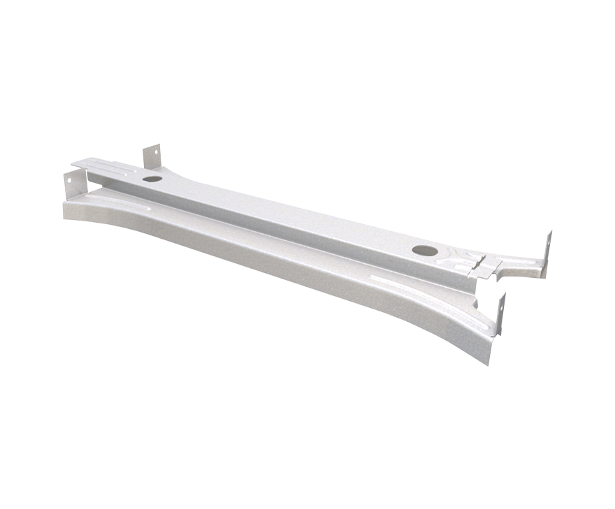
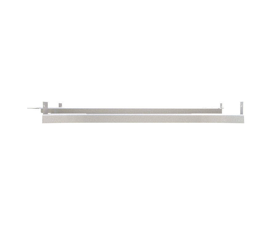
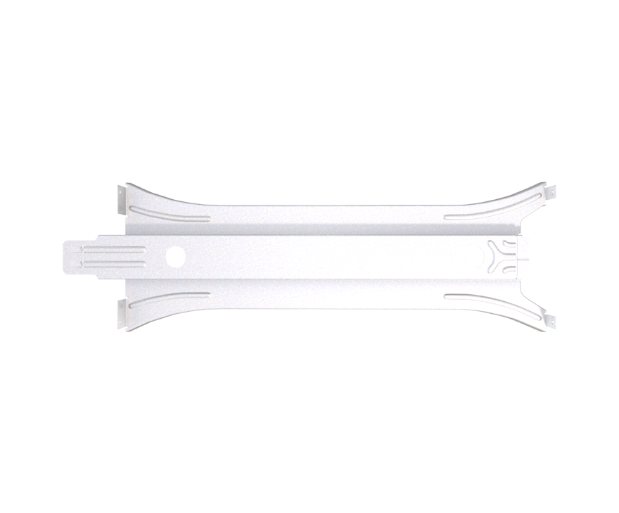
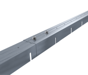
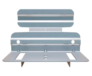
BuckleBridge® Solid Bridging System
Features
- Fast installation
- Tabs lock into slots for continuous system
- No threading channels through knockouts
- No welding
- Meets AISI bridging stiffness requirements
- Guide holes for accurate placement of fasteners to stud
- Fits in SigmaStud® and standard “cee” wall sections, 6” and 8″ web depths
- Reduces required rows of bridging when compared to other bridging methods such as cold-rolled channel with clips
Material Composition
Catalogs
TSN’s Product Catalogs are an essential resource for the design of cold formed steel. Developed by Engineers, the catalogs contain design data for members, connectors, and fasteners. BuckleBridge® can be found in the following Catalogs:
|
|
|

For a full list of our product catalogs, specification sections, inspection checklists, and research reports please click here.
BuckleBridge® provides continuous bridging at 16″ o.c. to resist weak-axis buckling and torsional forces. Explore full technical charts and standards in our Cold-Formed Steel Bridging Design Guidelines.
Order Information
Nomenclature
BuckleBridge comes in one size and is designated BuckleBridge®. It is used with 16″ o.c. member spacing.
BuckleBridge Downloads

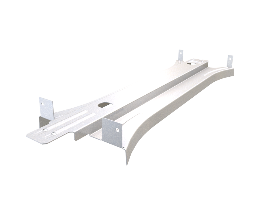
BuckleBridge® Applications
When using BuckleBridge in curtain walls with standard “cee” studs, one screw is only needed every 3rd stud. BuckleBridge can also be used in load bearing walls with TSN’s SigmaStud® or in floors using TSN’s PrimeJoist.
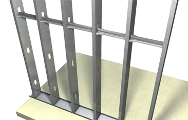
"CEE" Stud Curtain Wall Bridging Application
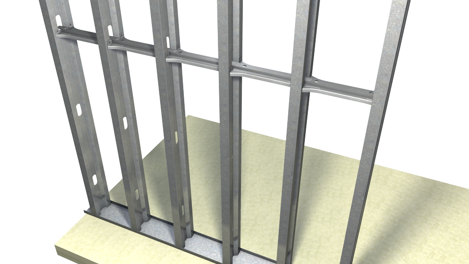
SigmaStud Wall Bridging Application

PrimeJoist Floor Bridging Application
Installation Instructions
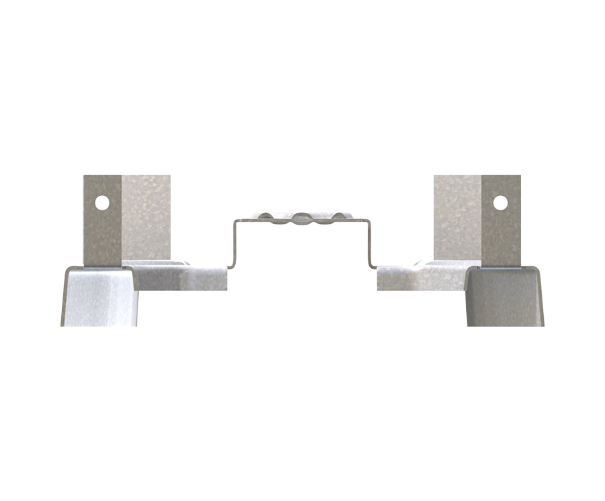
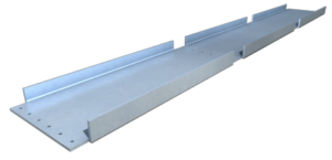
- Twist BuckleBridge into stud punchout and insert tab into slot of previously installed BuckleBridge.
- Install #10 screws through guide holes to stud web where applicable.
- For curtain wall applications, use (1) #10 screw on alternate sides of the BuckleBridge at 3rd stud (48″ o.c.) Use (2) #10 crews at end of wall run.
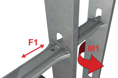
Allowable Loads
| BuckleBridge® Allowable Loads | ||||||
| Studs 16″ o.c. | Axially Loaded Studs | Laterally Loaded Studs | ||||
| Compression Brace | Tension Brace | 6″ Studs | 8″ Studs | |||
| F1 (lbs) | Stiffness (lbs/in) | F1 (lbs) | Stiffness (lbs/in) | M1 (in-lb) | M1 (in-lb) | |
| 2,400 | 31000 | 440 | 2,560 | 1,290 | 967 | |
Notes:
- Allowable load tables incorporate eccentric loading of fasteners. Values with welded connection may increase.
- Fasten within ¾” from the angle heel (centerline of the 1½” leg) to minimize eccentric load transfer.
- Fasteners attaching clip to structure should be installed symmetrically around the center line of the clip. The allowable load of the clip may be reduced if fasteners are not installed symmetrically.
- Guide holes in the 1½” leg measure 0.141″ in diameter.
- Total vertical deflection of up to 2″ (1″ up and 1″ down).
- Allowable loads have not been increased for wind, seismic, or other factors.
- MasterClip VLB resists horizontal and vertical loads when used as a rigid connector.
- Loads listed reflect force in a single direction. When multiple loads react on the connection, it is the responsibility of the designer to check the interaction of forces.
- Torsional effects are considered on screw group for F3 allowable loads. It is assumed that half of the torsional moment is taken by the connection to the structure and half is taken by the connection to the stud.
- Design loads consider loads on the clip and #12 screw fasteners to the stud web.
- (3) #12 screws are provided with each connector to be used for either vertical deflection connector or rigid connector step bushing. Load requirements don’t always justify use of all screws provided.
- Three slots are standard in 6″ and higher web depths to accommodate construction tolerances. Use of a 3rd screw and bushing is dependent upon load configuration.
Screw Patterns
* Important Consideration: Pattern diagrams indicate fastener placement only. Each standard StiffClip LB product comes with 4 guide holes to stud.
Load Direction
More Bridging Members & Connectors
Follow us on Social Media
