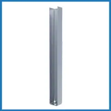
MidWall™ Partial Wall Framing
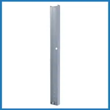
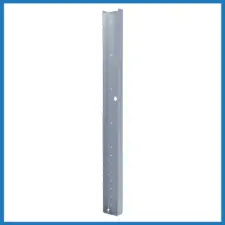
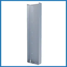
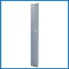
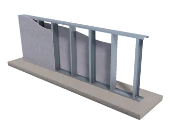
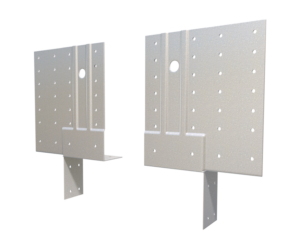
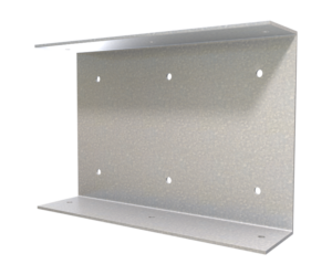
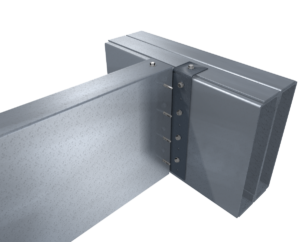
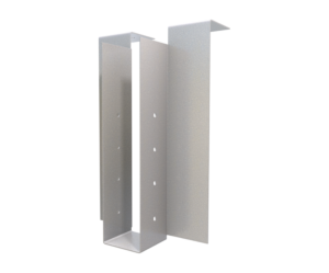
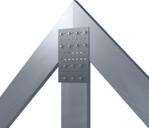
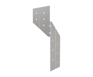
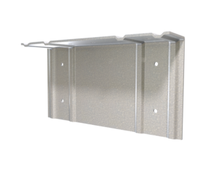
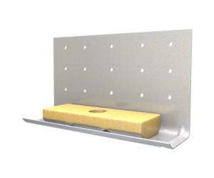
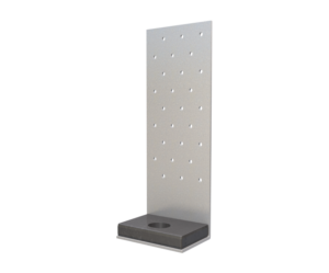
MidWall is designed to support out-of-plane loading in cantilevered partial wall systems that are unsupported at the top track like pony or knee walls. The out-of-plane loads are transferred to the floor system through a ½” thick plate nested in the flanges of the member with two ⅜” diameter fasteners (or [one] ½” diameter fastener for 250MW) used for the connection. Available in two lengths, 24″ and 48″, MidWall may be used in place of standard framing members, or in conjunction with them to frame the wall.
Features
- Replaces labor/coordination of placing embedded angle into floor system
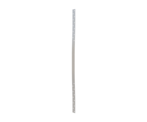
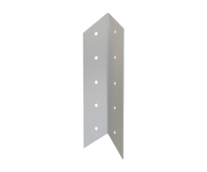
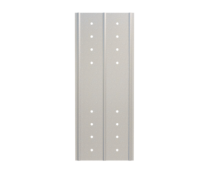
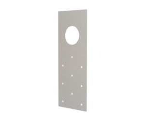
- Guide holes for attachment of MidWall to the stud
- Only certified steel is used
- 3.625″ and 6″ Meets IBC 2021 criteria Section 1607.9.1
- Test data for 2.5″ depth MidWall is available
Material Composition
MidWall: ASTM A1003/A1003M Structural Grade 50 (340) Type H, ST50H (ST340H), 50ksi (340MPa) minimum yield strength, 65ksi (450MPa) minimum tensile strength, G90 (Z275) hot-dipped galvanized coating. Material Thickness = 118mil (10 gauge, 0.1242″ design thickness) for 250MW and 362MW. Material Thickness = 97mil (12 gauge, 0.1017″ design thickness) for 600 MW.
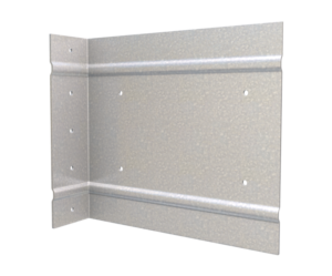
MidWall Plate: ASTM A36/A36M: 36ksi (250MPa) minimum yield strength, 58-80ksi (400-550MPa) tensile strength, ½” minimum thickness.
Catalogs
TSN’s Product Catalogs are an essential resource for the design of cold formed steel. Developed by Engineers, the catalogs contain design data for members, connectors, and fasteners. MidWall for pony or knee walls can be found in the following Catalogs:
|
|
|

For a full list of our product catalogs, specification sections, inspection checklists, and research reports please click here.


Order Information
Nomenclature
MidWall™ is currently available in two heights* (24″ and 48″) and three depths (2.5″, 3.625″, & 6″). Product nomenclature lists the member depth first followed by the height in inches.
Example: 6″ web depth, 24″ tall MidWall
Designate: 600MW-24
* Custom lengths available on request.
MidWall® Downloads

MidWall™ Applications
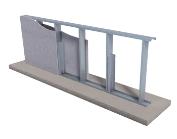
24" Pony / Knee Wall
MidWall 24″ is generally used in interior half walls of less than 48″ in height. Attach MidWall 24″ to a 54mil stud with #12 screws through all pre-drilled guide holes. Other studs in the walls are typical infill studs. Maximum spacing between MidWall connectors is 36″ o.c. Contact TSN Technical Services at (888) 474-4876 for design recommendations.
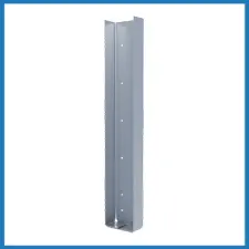
48" Pony / Knee Wall
MidWall 48″ is used in interior half walls equal to or more than 48″ in height. Use one MidWall 48″ as a substitute for a stud at the specified spacing, or attach to a 54 mil stud with #12 screws through all pre-drilled guide holes. Maximum spacing between MidWall connectors is 36″ o.c., or per design. Contact TSN for technical support regarding use in exterior walls.
Installation Instructions
- Place MidWall 24″ against stud web. Place base plate to anchors through pre-drilled guide holes.
- Fasten anchor to floor with specified washers.
- Attach MidWall 24″ to the stud web with #12 screw fasteners through guide holes (fill all holes in the vertical MidWall leg).
Allowable Loads
Notes:
- MidWall is designed to support out-of-plane loading in cantilevered partial wall systems that are unsupported at the top track.
- Out-of-plane loads are transferred to the floor system through plate nested in the flanges of the member with two ⅜” diameter fasteners (or one ½” diameter fastener for 250MW) used for the connection.
- MidWall may be used in place of standard framing members, or in conjunction with them to frame the wall.
Related Projects

More Rigid Connectors
Follow us on Social Media
