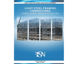
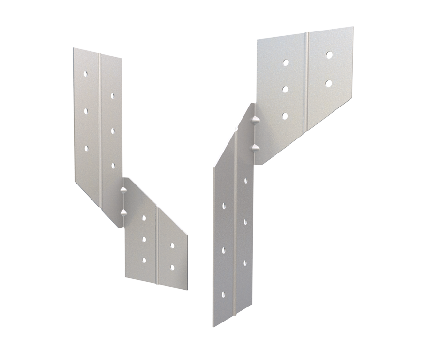
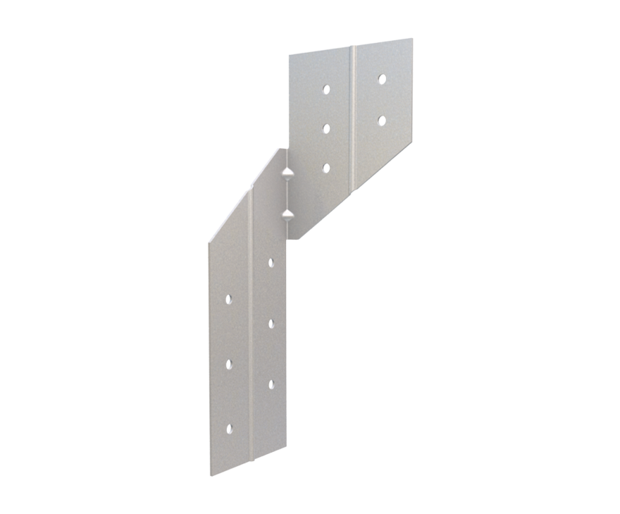
StiffClip® RT Roof Tie
Features
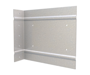
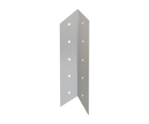
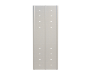
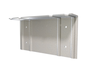
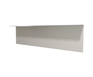
- Stiffened ribs for added strength
- Guide holes for attachment to framing members (0.188” dia.)
- Engineered for steel members
- Structurally load tested
- Meets all building code criteria
Material Composition
33 mil & 43mil Thicknesses: ASTM A1003/A1003M Structural Grade 50 (340) Type H, ST50H (ST340H): 50ksi (340MPa) minimum yield strength, 65ksi (450MPa) minimum tensile strength, with ASTM A653/A653M G60 (Z180) hot dipped galvanized coating.
54 mil Thickness: ASTM A1003/A1003M Structural Grade 50 (340) Type H, ST50H (ST340H): 50ksi (340MPa) minimum yield strength, 65ksi (450MPa) minimum tensile strength, with ASTM A653/A653M G90 (Z275) hot dipped galvanized coating.
Catalogs
TSN’s Product Catalogs are an essential resource for the design of cold formed steel. Developed by Engineers, the catalogs contain design data for members, connectors, and fasteners. StiffClip® RT can be found in the following Catalogs:
|
|
|

For a full list of our product catalogs, specification sections, inspection checklists, and research reports please click here.
Order Information
Nomenclature
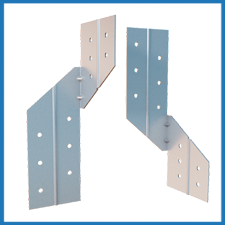
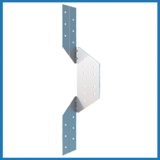
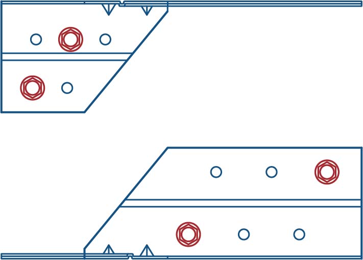
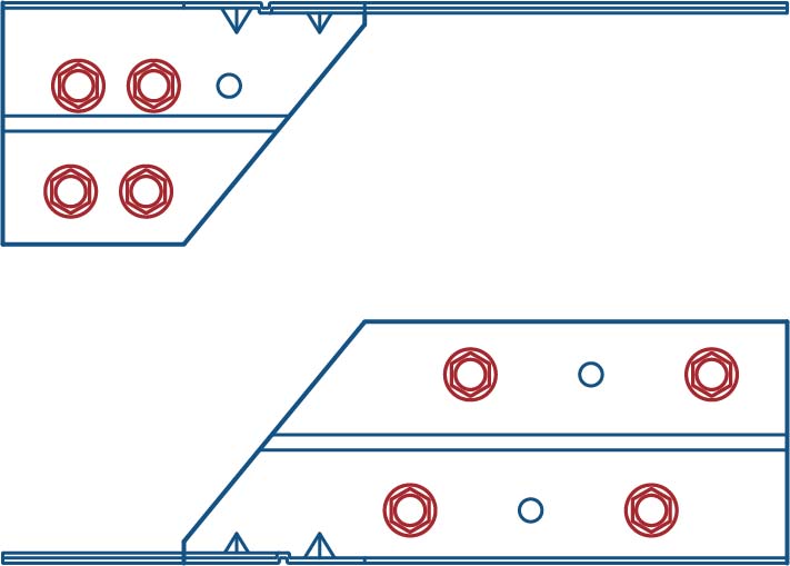
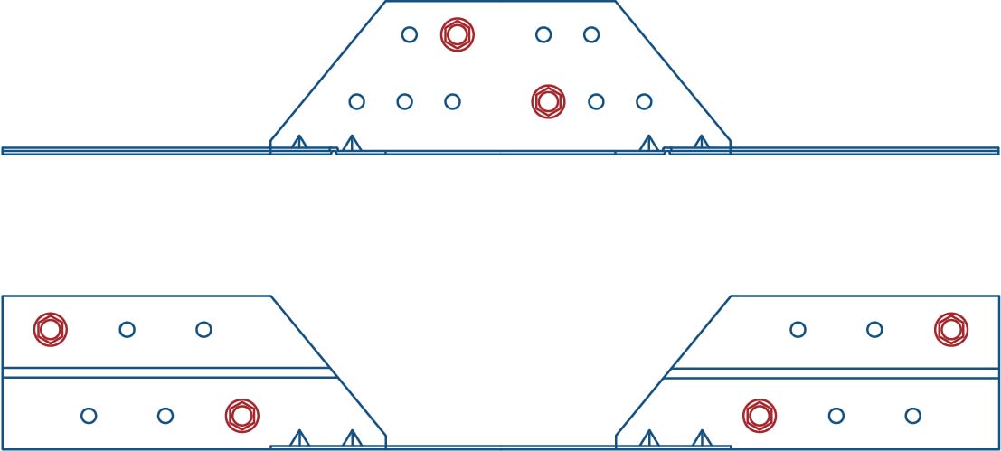
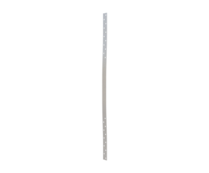
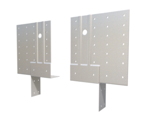
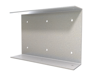
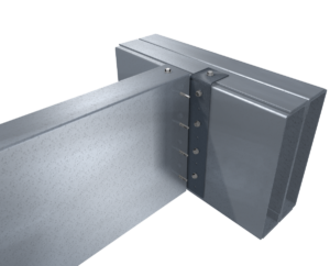
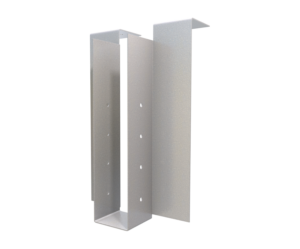
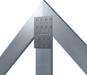
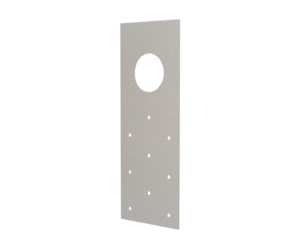
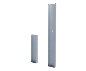
StiffClip RT650 is 6½” long, and may be used when wall studs do not align with roof framing member. The RT1300 is 13″ long, and is used when wall studs align with roof framing member. Clips are designated by length, followed by thickness and number of screws used in each leg (determined by load requirements – refer to load tables).
Example: Stud aligns with roof framing member (see application image)
Designate: StiffClip® 1300
* StiffClip RT650 are packaged in pairs. (shown right)
StiffClip® RT Downloads

StiffClip® RT Applications
The unique design of MasterClip allows it to be installed either as a vertical deflection connection or a rigid connection. Attachment to the primary structure may be made with a PAF, screw/bolt anchors, or weld and is dependent upon the base material (steel or concrete) and the design configuration.
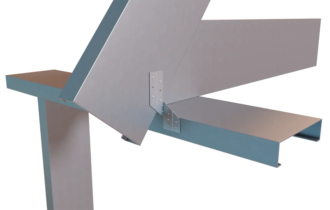
StiffClip RT650 - Roof Tie Application
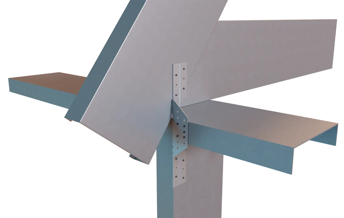
StiffClip RT1300 - Roof Tie Application
Installation Instructions
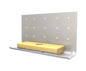
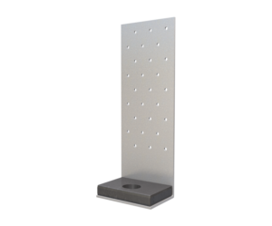
- To install the StiffClip RT, place one end flush against the roof framing member with the other end abutting the wall framing member.
- Attachment includes 2 or 4 screws in the upper and lower parts of each StiffClip RT.
Allowable Loads
RT1300-33
 2 Screws
RT1300-33
 4 Screws
RT1300-43
2 ScrewsRT1300-43
4 ScrewsRT1300-54
2 ScrewsRT1300-54
 4 Screws
RT1300-33
RT1300-33
RT1300-43
RT1300-43
RT1300-54
RT1300-54
RT1300-33
2 ScrewsRT1300-33
4 ScrewsRT1300-43
 2 Screws
RT1300-43
4 ScrewsRT1300-43
2 ScrewsRT1300-43
4 ScrewsRT1300-54
2 ScrewsRT1300-54
4 ScrewsLoad Table Notes
- Design loads are for attachment of StiffClip RT to light gauge framing members only. Load tables reflect in plane of wall loads (F1), horizontal loads (F2) and vertical uplift loads (F3).
- Number of screws designated represent the amount of #12 screws required in each leg of clips.
- Loads listed reflect force in a single direction. When multiple loads react on the connection, it is the responsibility of the designer to check the interaction of forces.
- Torsional effects are considered on screw groups for F1, F2, and F3 allowable loads. It is assumed that half of the torsional moment is taken by the connection to the structure and half is taken by the connection to the stud.
- Allowable loads have not been increased for wind, seismic, or other factors.
- StiffClip RT650 is available in a Left version and Right version. Contact TSN for ordering assistance.
- For LRFD strengths contact TSN technical services.
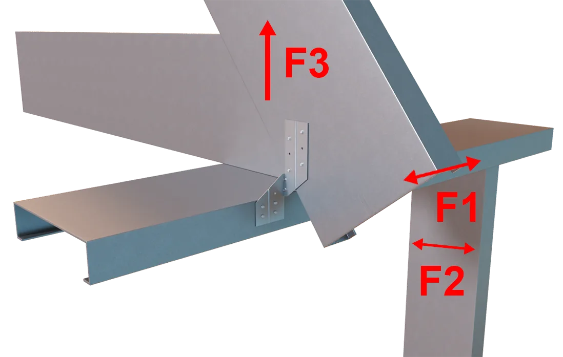
StiffClip RT650 Load Directions
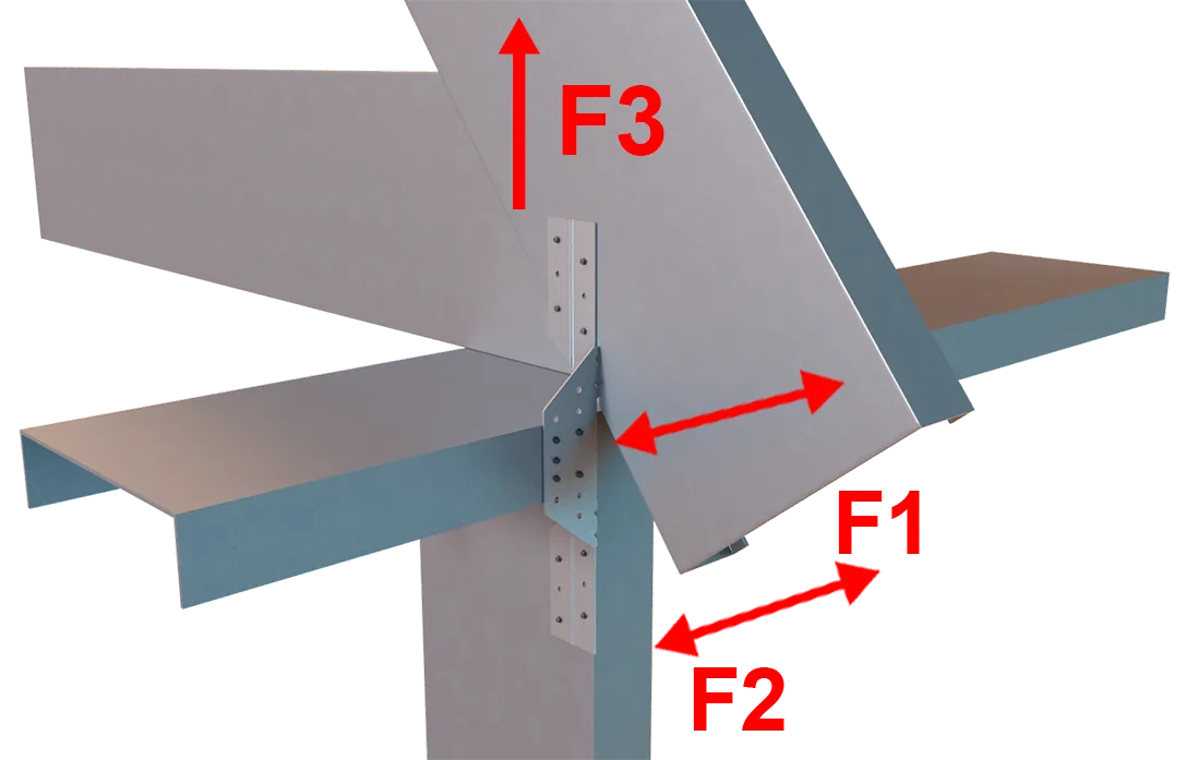
StiffClip RT1300 Load Directions
More Rigid Connectors
Follow us on Social Media
