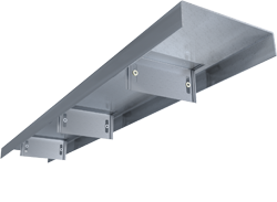
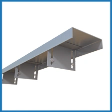
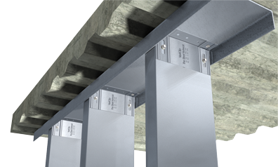
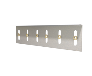
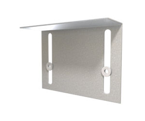
VertiTrack® VTD Interior Head of Wall
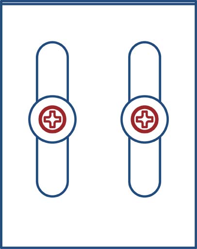
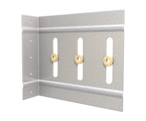
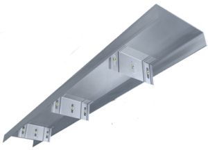
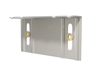
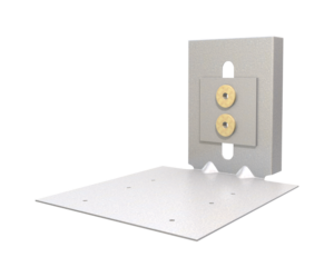
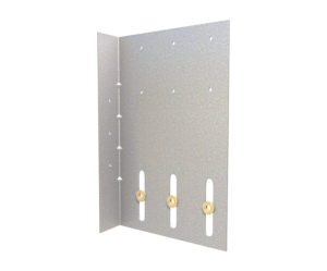
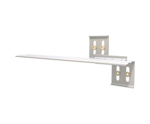
This deflection track system with preinstalled VertiClip® SLD’s, is used to connect the interior/exterior metal studs at head of wall to the primary structure while allowing for a vertical deflection of the structure up to 1½” (¾” up & ¾” down). A VertiClip® SLD is pre-installed to the track at 16” or 24”o.c. TSN’s patented Step Bushing Technology® provides an anti-friction and anti-seizure connection between the clip and the stud web surface.
Features
- NY MEA Approved, report #326-06-M
- Pre-installed clip saves time installing clips and spacing studs
- Load-rated positive mechanical attachment at each stud
- Patented Step Bushing Technology® provides friction-free motion for smooth vertical deflection
- Eliminates loose friction-held assemblies, heavy deep-leg track, & top row of wall bridging/strapping
- Load-rated #12 screws provided for vertical deflection connection to stud web
- Track manufactured with minimum certified 33mil, 33ksi, G60 coated cold-formed steel
- Clips manufactured with minimum certified 33mil, 50ksi, G60 coated cold-formed steel
Material Composition
Clip Material: ASTM A1003/A1003M Structural Grade 50 (340) Type H, ST50H (ST340H): 50ksi (340MPa) minimum yield strength, 65ksi (450MPa) minimum tensile strength, 33mil minimum thickness (20 gauge, 0.0346” design thickness) with ASTM A653/A653M G60 (Z180) hot dipped galvanized coating.
Track Material: ASTM A1003/A1003M Structural Grade 33 (230) Type H, ST33H (ST230H): 33ksi (230MPa) minimum yield strength, 45ksi (310MPa) minimum tensile strength, 33mil minimum thickness (20 gauge, 0.0346” design thickness) with ASTM A653/A653M G60 (Z180) hot dipped galvanized coating.
Catalogs
TSN’s Product Catalogs are an essential resource for the design of cold formed steel. Developed by Engineers, the catalogs contain design data for members, connectors, and fasteners. VertiTrack® VTD can be found in the following Catalogs:
|
|
|
For a full list of our product catalogs, specification sections, inspection checklists, and research reports please visit our Catalogs & Design Guides page.
Order Information
Nomenclature
VertiTrack VTD is manufactured in 12 ft. lengths. VertiTrack is designated by type (VTD), followed by stud depth in inches multiplied by 100 and stud spacing.
Example:6″ deep stud, 16″ on center
Designate:VertiTrack® VTD600-16
VertiTrack® VTD Downloads

VertiTrack® VTD Applications
The attachment of VertiTrack VTD to the primary structure may be made with PAFs, screw/bolt anchors or weld and is dependent upon the base material (steel or concrete) and the design configuration.
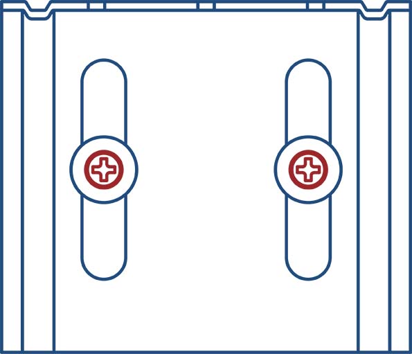
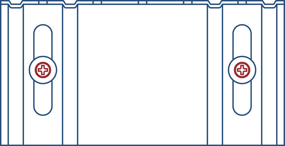
1½” Deflection - Interior or Exterior Head of Wall
Installation Instructions
- Attach VertiTrack VTD to deck with approved fasteners.
- Attach VertiClip through Step Bushings to wall studs with self-drilling screws provided.
Allowable Loads
w/2 #8 screws
w/2 #8 screws
w/2 #8 screws
w/2 #8 screws
Notes:
- VertiTrack VTD loads are the same as VertiClip SLD.
- VertiTrack VTD is assembled with the VertiClip SLD pre-attached at 16″ o.c. or 24″ o.c.
- VertiTrack VTD is designed to support horizontal loads, and should not be used in axial load-bearing walls.
- Allowable loads have not been increased for wind, seismic, or other factors.
- Strengthening ribs are present in 3-5/8″ and 6″ sizes.
- #8 screws are provided with each step bushing for attachment to the stud web.
- Fasten through each Verticlip SLD to structure.
- Fasten within 3/4″ of the angle heel (centerline of the 1-1/2″ leg) to minimize eccentric load transfer.
- Total vertical deflection of up to 1-1/2″ (3/4″ up and 3/4″ down). Deflection requirements greater than 3/4″ (up and down) are available. Custom spacing is also available.
- For LRFD strengths contact TSN technical services.
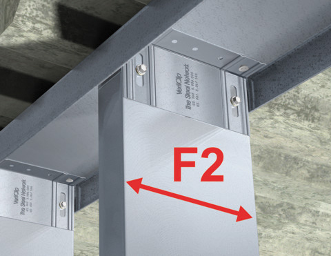
Load Direction
More Vertical Deflection Slide Angle & Track


Follow us on Social Media
