BackIt® Wall Backing
Features
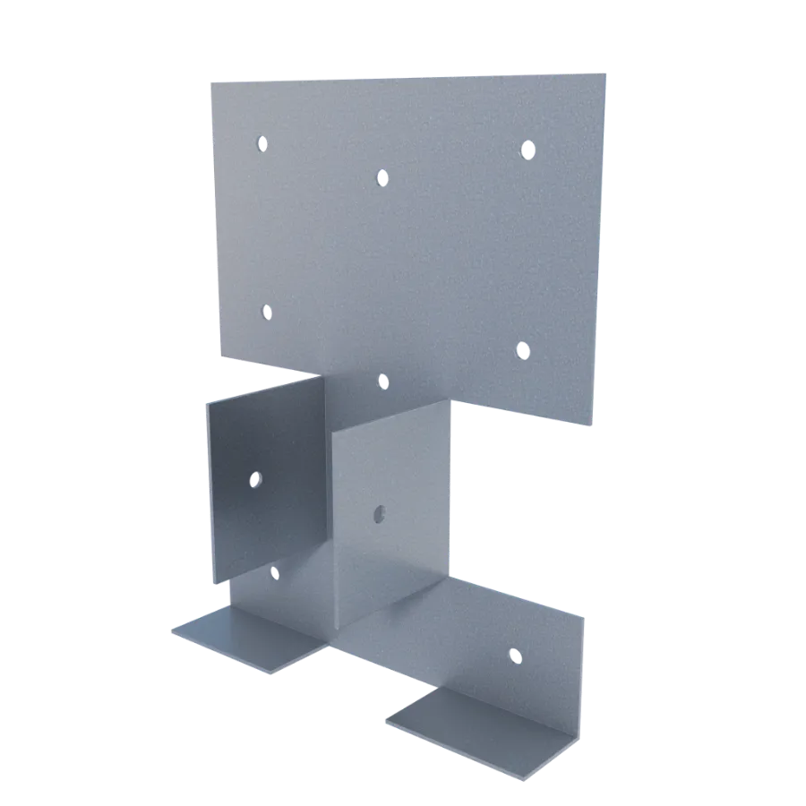
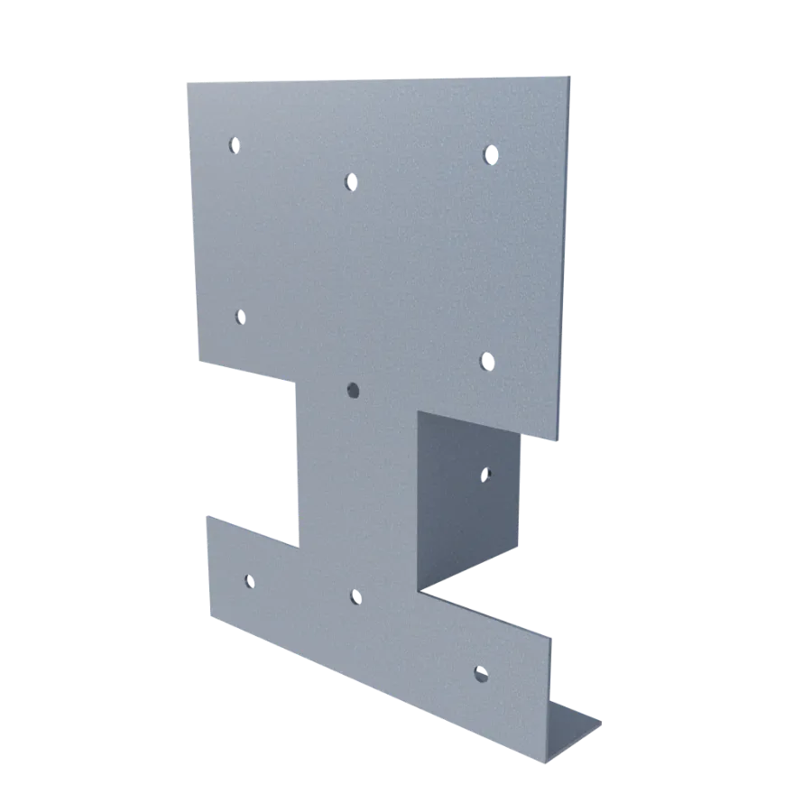
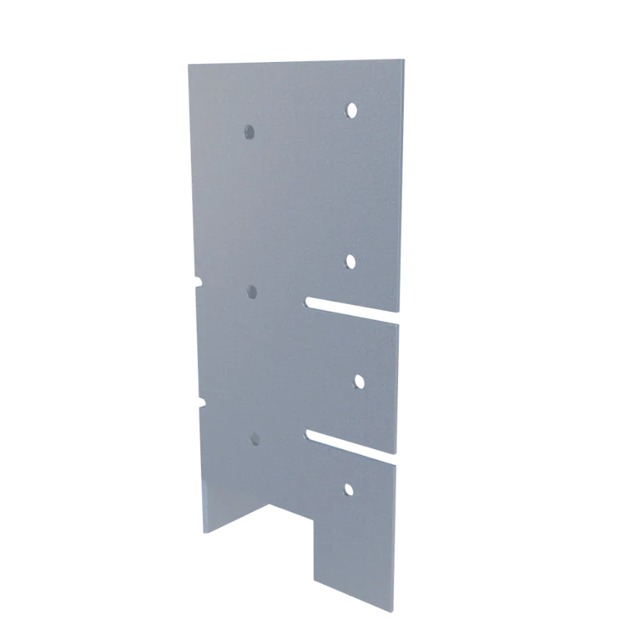
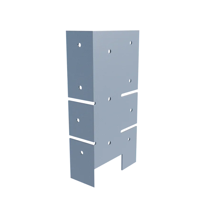
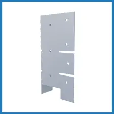
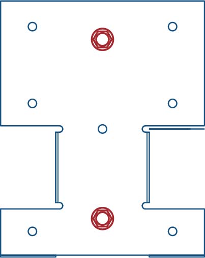
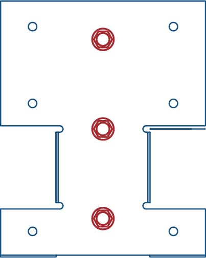
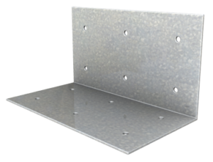
- Guide holes for stud and wood attachments
- Shelf tabs to rest wood upon during installation
- No pre-determined stud layout
- May be used with multiple sizes of wood
- Resists load in the directions recommended by codes
Material Composition
Catalogs
TSN’s Product Catalogs are an essential resource for the design of cold formed steel. Developed by Engineers, the catalogs contain design data for members, connectors, and fasteners. BackIt® can be found in the following Catalogs:
|
|
|

For a full list of our product catalogs, specification sections, inspection checklists, and research reports please click here.
Order Information
Nomenclature
BackIt is designed to be used with studs having flanges up to 1-5/8″ wide,* & is designated BackIt®
* Custom clips are available by request for use with studs having flanges greater than 1⅝”
BackIt® Downloads

BackIt® Applications
The unique design of MasterClip allows it to be installed either as a vertical deflection connection or a rigid connection. Attachment to the primary structure may be made with a PAF, screw/bolt anchors, or weld and is dependent upon the base material (steel or concrete) and the design configuration.
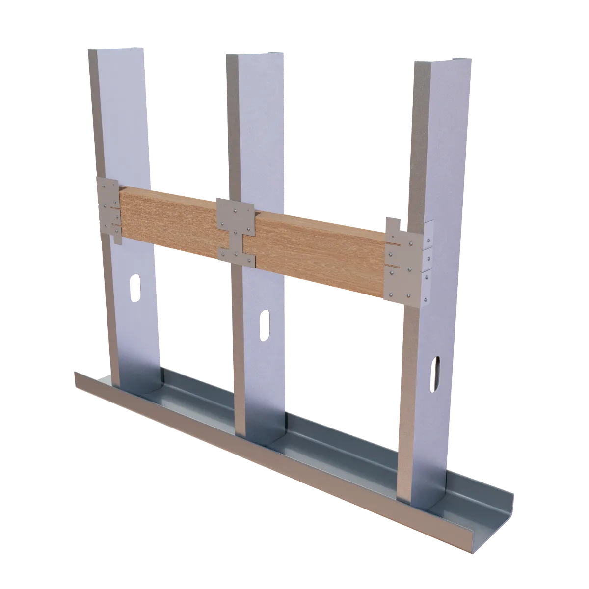
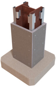
Solid Wall Backing for Handrails, Shelving, & Wall Mounted Equipment
Installation Instructions
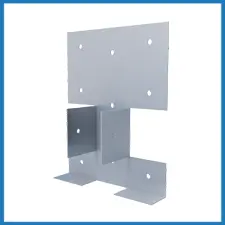
- Place clip flush against wall stud flange and attach to stud with required amount of approved fasteners. Fastener amounts may vary by application.
- Rest wood piece on shelf legs and attach to clip with required number of screws through guide holes. For higher loads, attach BackIt to the stud web through a guide hole in the interior leg.
Allowable Loads
The recommended allowable loads and moments reported in this table are for the clip and attachment to the stud only. The attachment to the backing material must be designed by a design professional.
IBC (International Building Code) and OSHA (Occupational Safety and Health Administration) load requirements include the ability of wall backing to resist a minimum of 200lbs of concentrated load, or 50lbs per linear foot in any direction. BackIt® satisfies the load requirements in vertical (F3) and horizontal (F2) directions. Extra testing has been done in the rotational (M1) direction. Product test reports are available upon request. Contact TSN Technical Support at (888) 474-4876 for more information.
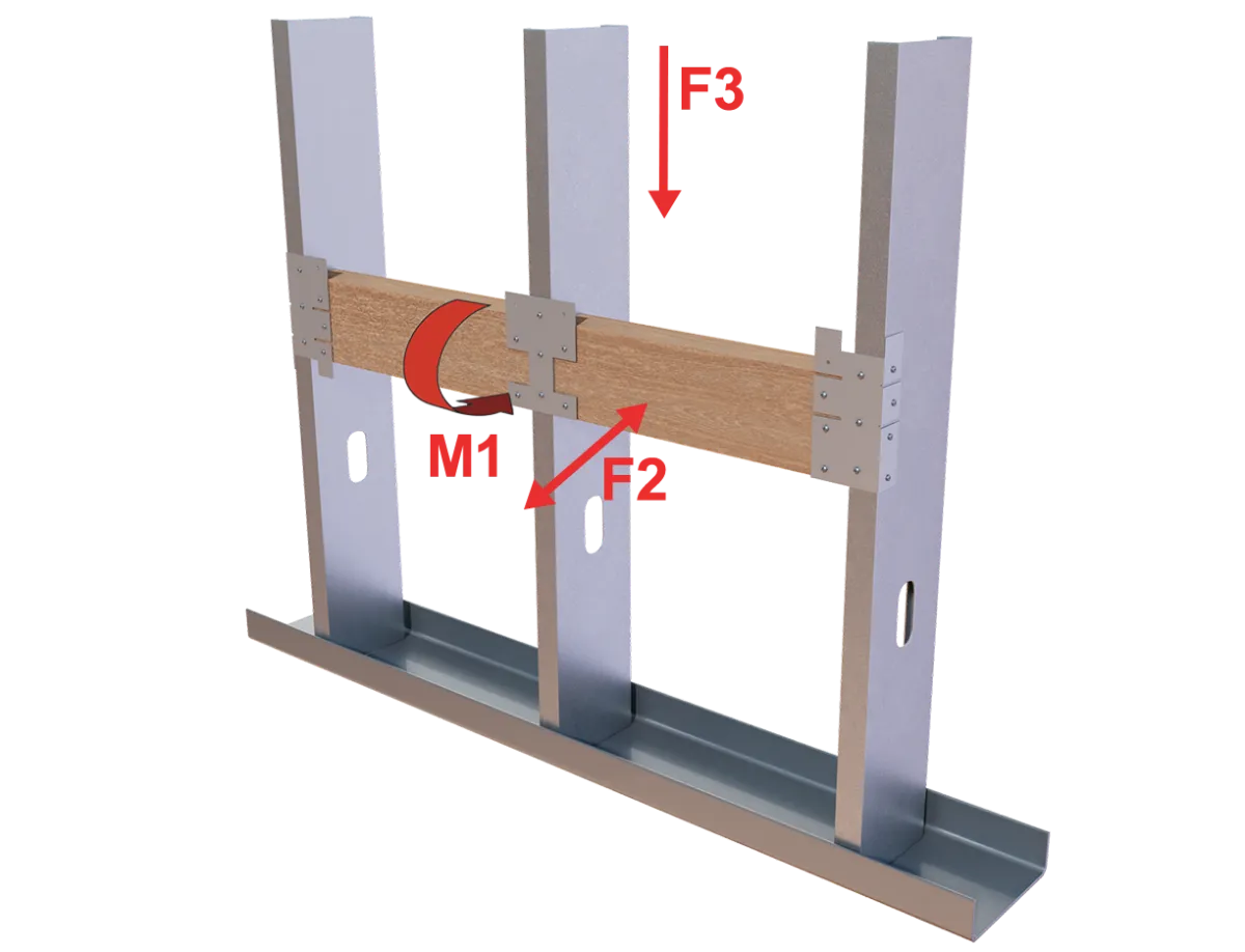
Load Direction
2 Screws
3 Screws
2 Screws
3 Screws
3 Screws
Up to 0.02 rad
Load Table Notes
- The recommended allowable loads and moments reported in this table are for the clip and attachment to the stud only. The attachment to the backing material must be designed by a design professional
- For LRFD strengths contact TSN technical services.
* Additional screws may be added to increase the allowable load. F2 value with (4) #12 screws is 207 lbs.
More Specialty Connector Members
Follow us on Social Media
